A few years ago, during a rapid prototyping review for an industrial client, I heard a question that still shapes how I start every job. We had just shown him a beautiful SLA model of a handheld meter housing. It was smooth, primed and painted in the exact gray from his brand book. He turned it over in his hands, nodded, and then asked, “So when can I drop it?”
In truth, he could not. Not that one. It was a looks like model, and as a result it would have cracked like a dinner plate on the shop floor. The model did exactly what we built it to do. However, we had never talked about what he actually needed to learn, or by when. That conversation cost us two weeks.
The Real Problem With Choosing Rapid Prototyping Methods
That, in short, is the real problem with rapid prototyping. The methods themselves are well documented, and every service bureau has a comparison chart. What usually gets skipped, though, is the harder question: what does this prototype need to prove, and how many weeks do you have to prove it? For that reason, I pick the method from the calendar backward, not from the catalog forward.
What follows, then, is how I make that call as an industrial designer, after a lot of prototypes that worked and a few that taught me something expensive.
What “Rapid” Really Means for Rapid Prototyping Methods
“Rapid” is a slippery word. For example, a print that comes off the bed overnight is rapid. Yet an aluminum mold that ships parts in three weeks is also called rapid, because the steel tool it replaces might take two or three months.
So when someone on a team says “let’s rapid prototype it,” I ask them to say a number instead. Days? Weeks? And, just as important, how many parts?
Those two numbers, lead time and quantity, eliminate most options before we ever talk about material. In addition, the third number is fidelity: how close the prototype has to be to the production part in material, finish and tolerance. In my experience, most bad prototyping decisions come from optimizing one of those three while ignoring the others.
Naming the Job Behind Rapid Prototyping Methods
I also find it useful to name the job each prototype is doing. Therefore, the language I use with clients is simple:
Looks like models answer questions about form, proportion, color and how a product sits in the hand or on a bench.
Works like models, by contrast, answer questions about mechanisms, fit, airflow, heat, load and assembly.
Is like models (some teams call them pre production or validation parts) finally answer the last question: will the real process, in the real material, give us the part we designed?
Consequently, each job points toward a different method, and each method fits a different window on the calendar.
The Five Rapid Prototyping Methods I Actually Use
There are dozens of processes out there, such as laminated object manufacturing, PolyJet, binder jetting and soft lithography for microfluidics. Admittedly, they all have a place. For industrial products, however, five families cover almost everything I build, and each has its own personality.
1. 3D Printing: The Fastest Way to Be Wrong Cheaply
Why Printing Comes First
Additive manufacturing is where nearly every project of mine starts. In fact, it is the method most people mean when they say rapid prototyping. The speed is real, too. For instance, Formlabs describes a 24 hour loop where a team designs in CAD during the day, prints overnight, then cleans and tests the part the next morning. I have lived that loop for weeks at a time, and frankly nothing else lets you iterate a grip or a bezel that quickly. Just remember that in house printers on the plant network need the same OT security rules as any other connected machine, which whoever handles your manufacturing IT services can set up.
Even so, “3D printing” is not one method. Rather, it is at least four, and they behave very differently.
FDM for Rough Fit Checks
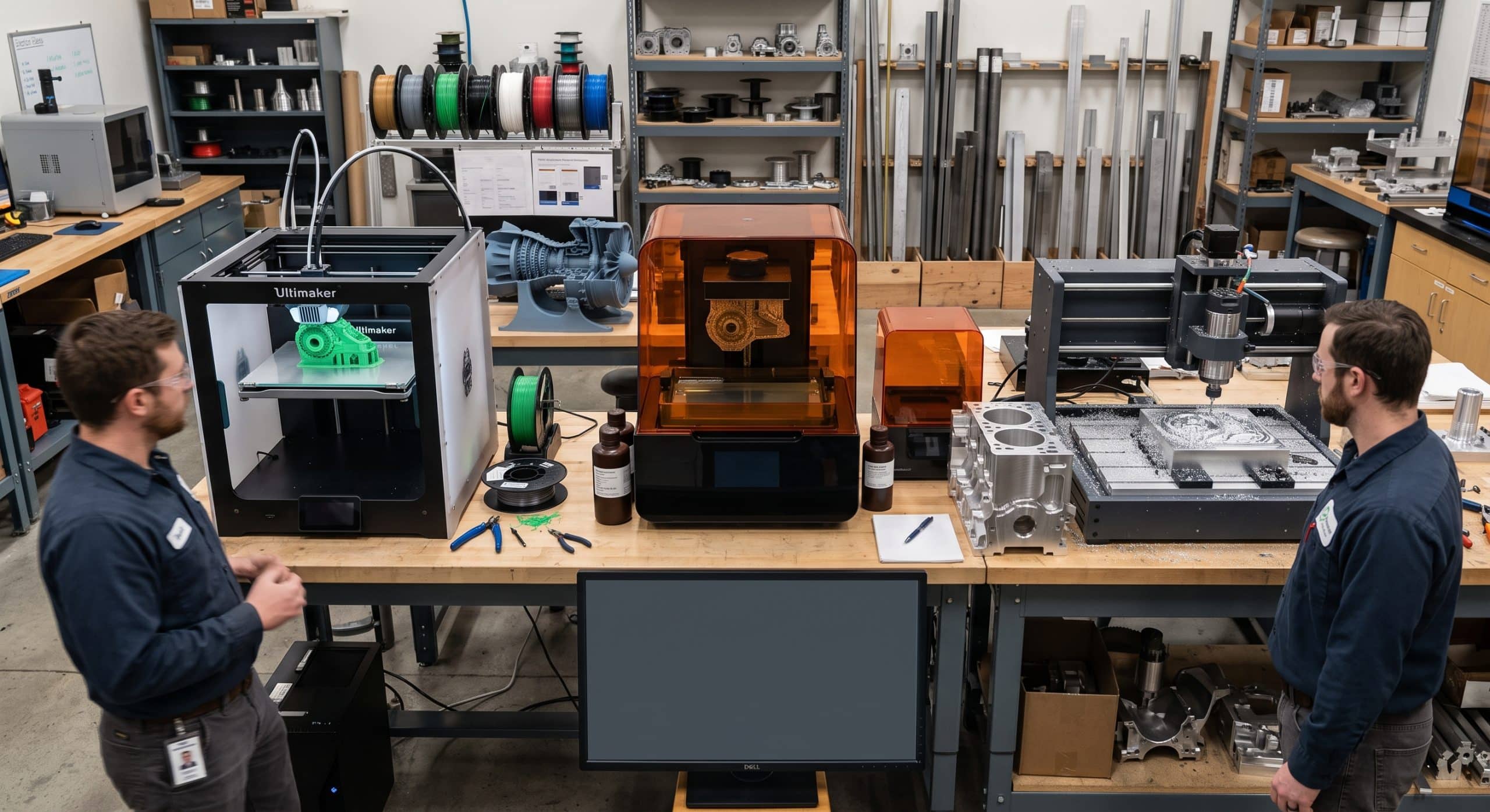
FDM (fused deposition modeling) is the workhorse for rough concept and fit checks, mainly because it is cheap and forgiving. Similarly, the Hubs knowledge base makes the point that when an electronics enclosure is being prototyped and mechanical strength is not the main concern, desktop FDM is usually the most efficient route. The tradeoff, however, is visible layers and weaker bonds between those layers. As a result, I never trust an FDM part to tell me the truth about snap fits or impact.
SLA for Detail and Finish
SLA (stereolithography), on the other hand, gives me the surface quality I need for presentation models and fine detail. Protolabs lists typical SLA layers at roughly 0.002 to 0.006 inch, which explains why SLA parts can be sanded and painted to look like finished goods. Unfortunately, that same finish is the trap I described in the opening. Standard resins are brittle, and so a gorgeous part can lead stakeholders to believe the design is further along than it is.
SLS and MJF for Functional Nylon
SLS and MJF (powder bed nylon processes) are where printing starts to become a real works like option. Specifically, you get nylon parts with no support structures, decent toughness and complex internal geometry. For this reason, I use them for brackets, clip features, ducting and anything with living hinges I want to cycle a few hundred times. Increasingly, some of these parts never leave the printer at all, as industrial printing moves beyond prototypes into end use production.
Metal Printing for Geometry You Cannot Machine
Metal printing (DMLS or SLM) earns its keep when the geometry simply cannot be machined, such as internal cooling channels, lattices or consolidated assemblies. Outside those cases, though, it is usually slower and more expensive than machining the same part. Likewise, Fabcon reports that metal 3D printing often costs 50 to 70 percent more than CNC machining for mid complexity parts, and that it struggles once quantities climb past 10 or 20 units.
Where Printing Fits on the Timeline
Overall, printing owns days one through roughly week four. It is the right answer when the design is still moving, when you need many variations side by side, or when geometry is complex. Conversely, it is the wrong answer when the test depends on real material behavior.
2. CNC Machining: When the Prototype Has to Tell the Truth
Real Material, Real Results
When a prototype needs to carry load, hold a tight bore, seal against a gasket or survive a drop test, I move to machining. After all, CNC cuts the part from the same billet or plate stock that production may use, whether that is aluminum 6061, stainless, Delrin, PEEK or polycarbonate. In other words, the material properties are not approximations.
The Price of Honesty
Naturally, the cost of that honesty is time and setup. Someone has to program toolpaths, fixture the part and run it. The Hubs guidance is blunt on this: CNC is the stronger choice for precision, smooth surfaces and tight tolerances, while printing wins on complex shapes and pure iteration speed. (I cover the printing versus machining tradeoffs in more depth separately.) Furthermore, Protolabs adds a volume angle I agree with: for runs of around 100 or more parts with fairly simple geometry, machining is usually the logical choice.
Advice for Junior Designers
One thing I always tell junior designers is that CNC is not just for metal. For example, a machined acetal gear or a machined polycarbonate window will tell you far more about wear and clarity than any printed stand in.
There is also a design discipline benefit. If you prototype in CNC and the machinist calls you about a deep pocket or an internal corner radius, listen. That call is essentially free design for manufacturing feedback, and moreover it often foreshadows problems your molder will raise later.
Where CNC fits on the timeline: typically weeks two through eight. Parts arrive in days rather than hours, so it pays off once the core geometry has stopped changing every afternoon.
3. Urethane Casting: The Small Batch Bridge Most Teams Forget
How the Process Works
Urethane casting (also called vacuum casting) is the method I wish more clients knew about. First, you build one excellent master pattern, often SLA or machined. Next, you cast a silicone mold around it, and then you pour polyurethane resins into that mold. Wikipedia’s overview notes that cast urethanes suit smaller runs and prototyping, and that master patterns are commonly made by 3D printing.
Why the Middle Zone Matters
Why does it matter? Because there is an awkward middle zone between “we need three parts” and “we need a thousand.” Think of field trials, trade show units, beta testers or a regulatory submission sample set. In each case, you need 20 or 50 parts that look and feel like production. Printing 50 SLA housings is slow and inconsistent. Meanwhile, cutting an aluminum mold is overkill and locks in the design.
Urethanes also come in rigid, clear and rubber like grades, and they can be color matched in the pour. As a result, parts come out with molded surface quality, close to what customers will eventually hold.
Cost Break Points to Remember
The cost logic is easy to remember. FacFox frames urethane casting as scalable from 1 to roughly 500 parts. In my own quotes, the pattern looks like this: from one to ten units, printing or CNC is usually cheapest since there is no tooling; between roughly 10 and 500 units, urethane casting usually wins on cost and lead time; and past 500, aluminum or P20 steel tooling starts to pay for itself. Granted, I treat those numbers as a rough map rather than a law. Still, they hold up more often than not.
Limits to Keep in Mind
That said, the limits are real too. Silicone molds wear out after a modest number of shots, and tolerances are looser than machining. Above all, urethane only mimics thermoplastics. It does not replicate how a glass filled nylon will warp in a hot steel mold.
Where urethane casting fits on the timeline: usually weeks four through ten, once the design is frozen enough to justify a master but before tooling is approved.
4. Sheet Metal Prototyping: The Method Industrial Teams Underuse
For enclosures, chassis, brackets, guards and panels, nothing replaces bending real metal. Indeed, a printed version of a bent bracket will lie about springback, about hole distortion near a bend, and about how a panel flexes when an operator leans on it.
Xometry points out that aluminum 5052 is the most common sheet metal material for rapid prototyping, and that sheet metal prototyping is valued for its fast turnaround on complete parts. In industrial equipment design, however, I would go further. If production is going to be sheet metal, then prototype in sheet metal as early as you sensibly can. After all, bend allowance mistakes found at the prototype stage cost an afternoon. Found at first article, by contrast, they cost a recut of the flat pattern and sometimes a press brake tooling change.
Where sheet metal fits on the timeline: almost anywhere after the first concept models. Because turnaround is often a few days to about a week, it is one of the most schedule friendly ways to get production truth.
5. Rapid Injection Molding: The Rehearsal Before Opening Night
Real Parts From Real Tooling
Rapid injection molding uses aluminum or soft steel tools, frequently built as inserts in a standard master unit die frame, to shoot real production thermoplastics. In other words, your prototype is no longer an imitation of an ABS part. It is an ABS part.
That is precisely where you discover things nothing else will show you: sink marks over thick ribs, warp on a long thin wall, knit lines that weaken a boss, and cosmetic gate blemishes on a show surface. In addition, it gives you hundreds or thousands of identical parts for life testing and pilot builds. Start tracking those pilot builds in your MES from the first run, so production starts with real data instead of a blank screen.
Lead Time and Commitment
The cost, however, is lead time and commitment. Xometry’s European service lists the usual rapid tooling lead time as about two to three weeks for initial parts. Likewise, its US quick turn option advertises prototype grade aluminum molds with up to 2,500 shots and lead times as short as five business days for parts that fit its limits. Since that shot life is finite, log prototype tools as assets in your CMMS so nobody is surprised when a mold wears out halfway through a pilot. For production tools later on, predictive maintenance sensors can warn you before a mold or press fails. Moreover, every change after the tool is cut means machining aluminum, and some changes (adding material back to the tool) are far harder than others.
My Rule for Cutting a Mold
For that reason, my rule is simple: never cut a prototype mold to answer a question a printed or machined part could answer. Instead, cut it when the remaining questions are about the molding process itself.
Where rapid injection molding fits on the timeline: generally the last third of development, once design changes have slowed to small, steel safe tweaks.
Rapid Prototyping Methods Side by Side
Here is the quick reference I give clients. Keep in mind that the lead times are typical ranges from my own projects and published service data, so your supplier, geometry and finish requirements will move them.
| Method | Typical lead time | Sweet spot quantity | Material truth | Best job |
|---|---|---|---|---|
| FDM printing | Hours to 2 days | 1 to 10 | Low | Rough fit, ergonomics, layout |
| SLA printing | 1 to 3 days | 1 to 10 | Low to medium | Looks like models, fine detail, master patterns |
| SLS / MJF nylon | 3 to 7 days | 1 to 100 | Medium | Functional clips, ducts, complex works like parts |
| CNC machining | 3 days to 2 weeks | 1 to 100+ | High | Load bearing, tight tolerance, real material tests |
| Urethane casting | 1 to 2 weeks | 10 to 500 | Medium to high | Pilot units, trade show and beta batches |
| Sheet metal | 3 days to 1 week | 1 to hundreds | High | Enclosures, brackets, panels, guards |
| Rapid injection molding | 1 to 4 weeks | 100 to thousands | Production grade | Process validation, pilot runs, bridge production |
Matching Rapid Prototyping Methods to Your Production Timeline
A chart tells you what each method can do. Your schedule, on the other hand, tells you which ones you can afford to use. Below are three timelines I see constantly, along with how I would sequence each.
The Two Week Sprint
This is the trade show deadline, the investor demo, or the “customer visit is on the 20th” scramble.
With two weeks, you get one, or maybe two, loops. Therefore, I go straight to the fastest processes and accept their limitations openly. I use SLA for anything that will be photographed or handled by visitors, SLS for anything that has to click, slide or hold, and off the shelf hardware wherever possible. Likewise, if a metal part is unavoidable, I keep it to simple geometry a local shop can machine in three or four days.
The discipline here is to be honest about what the demo proves. For that reason, I label these units internally as “show models” so nobody later mistakes them for validated hardware.
The Six to Eight Week Development Window
This is the most common window for industrial product refreshes and new accessories. Fortunately, it is long enough to do things properly.
Weeks one through three: First, run rapid FDM and SLA loops on form and layout, with multiple variants at once. Then let users and technicians handle them. This is, without question, the cheapest learning you will ever buy.
Weeks three through five: Next, shift critical parts to CNC or sheet metal, such as mounting brackets, load paths, sealing faces and hinge pins. Meanwhile, keep printing the parts that are still evolving cosmetically.
Weeks five through eight: Finally, if you need more than a handful of units for field evaluation, cast a urethane batch from a polished master. Also, if production is injection molded and volumes justify it, kick off DFM review with your molder now, even if the tool will not be cut until later.
The Twelve Week or Longer Path to Production
Longer programs, by contrast, earn the right to run methods in parallel, which is where the real time savings live.
For example, while the enclosure is still in printed iterations, the internal chassis can already be in sheet metal, because its interfaces were locked early. Similarly, while urethane units go out to field testers, the molder can be cutting an aluminum tool for the parts that have stopped changing. If the product will be assembled on an automated line, bring your industrial automation team in now, so fixtures and grippers are designed against real parts. This is also the point to set up part numbers, BOMs and routings in your manufacturing ERP, so the handoff to production does not stall on paperwork.
RapidDirect’s guide describes the familiar EVT, DVT and PVT gates. In their framing, early validation leans on 3D printing and fast iteration, whereas production validation moves to rapid injection molding and pilot runs. I think of it the same way, but with one extra rule: each part travels through those gates on its own clock. In other words, not every component needs to wait for the slowest one.
How Quantity Changes Which Rapid Prototyping Methods Win
Here is the conversation I try to have in the first week of a project: “How many prototypes will we need, in total, before launch?”
Admittedly, people rarely know. Nevertheless, asking forces a plan. One concept model? Five ergonomic variants? Twenty units for a beta site? Or two hundred for a certification lab and a sales team?
Quantity changes the right answer more than almost any other factor. The Hubs volume guide lays it out plainly: for plastics, it steers small quantities toward 3D printing, moderate quantities toward CNC with injection molding as a consideration, and larger volumes toward molding. Combine that with the urethane casting break points mentioned earlier, and as a result you get a simple ladder:
- Under 10 parts: print or machine.
- Ten to a few hundred: cast urethane, or machine if the material must be exact.
- Several hundred and up: start pricing aluminum tooling.
Even so, the mistake I see is teams building 30 SLA housings one by one because “printing is cheap.” Consequently, they spend more time and money than a single silicone mold would have cost.
Five Mistakes With Rapid Prototyping Methods That Wreck Schedules
After enough projects, the same failures show up again and again. Interestingly, none of them are about the machines.
1. Testing the wrong property with the wrong method. For instance, drop testing a printed resin housing and concluding the design is weak. Or, similarly, approving a snap fit in nylon that will be molded in polycarbonate. So always ask what the prototype material is lying about.
2. Letting the pretty model set expectations. A painted SLA part reads as “nearly done” to executives and customers. Therefore, put a label on it, literally if needed.
3. Cutting tooling too early. If the design review still has open questions about wall thickness or boss placement, then a mold is the most expensive possible way to answer them.
4. Ignoring the supplier’s feedback. DFM comments from a machinist, a sheet metal shop or a molder are free engineering. In fact, many digital manufacturers now return automated DFM analysis within minutes of upload, so read it before you click order. Before uploading, also confirm how the platform secures your design data off premises.
5. Prototyping parts in series that could run in parallel. If the bracket’s interface is frozen, make it in production metal now. In other words, do not wait for the cosmetic cover to finish its fifth iteration.
How I Choose Rapid Prototyping Methods in One Pass
When a client asks which method fits, I run through four questions in this order:
- What must this prototype prove? Look, function, or process.
- When do we need the answer? Days, weeks, or a month or more.
- How many units do we need? One, dozens, or hundreds.
- How close to production must the material be? Approximate, equivalent, or identical.
Answer those honestly, and the method usually picks itself. However, if two methods still compete, pick the one that gets the answer sooner and accept a second loop later. After all, a fast imperfect answer beats a slow perfect one almost every time in early development.
Final Thoughts on Rapid Prototyping Methods
Ultimately, rapid prototyping is not one technology. Instead, it is a sequence of decisions about what to learn, how fast, and at what level of truth. The best development programs I have worked on did not use the fanciest process. Rather, they used the right process at the right week, moved parts forward the moment their questions were answered, and never mistook a beautiful model for a validated one.
As for the client with the meter housing, he got his drop test eventually, in machined polycarbonate, three weeks later than it should have been. Happily, the design passed. Since then, though, I have opened every project with the same question he made me ask: what does this prototype have to survive?
Frequently Asked Questions About Rapid Prototyping Methods
What is the fastest of the rapid prototyping methods?
3D printing, especially FDM and SLA, is typically the fastest, with parts often available within a day when printed in house. Formlabs explains the overnight print cycle in its rapid prototyping guide.
Is CNC machining or 3D printing better for functional prototypes?
CNC machining is usually better when you need real material properties, tight tolerances and load bearing strength. By contrast, 3D printing is better for complex geometry and quick iteration. Hubs offers a detailed comparison.
When should I use urethane casting instead of 3D printing?
Use it when you need roughly 10 to a few hundred consistent parts with molded surface quality, such as pilot units or beta batches. See the cast urethanes overview for how the process works.
How long does rapid injection molding take?
First parts from prototype aluminum tooling commonly arrive in about two to three weeks, although some quick turn services are faster for small, simple parts. Xometry outlines typical timing on its quick turn injection molding page.
Can sheet metal be used for rapid prototyping?
Yes. In fact, sheet metal prototyping is one of the quickest ways to test enclosures, brackets and panels in their real material. Details are on Xometry’s sheet metal prototyping page.
How do I choose between rapid prototyping methods?
Start with what the prototype must prove, and then factor in deadline, quantity and material accuracy. Protolabs provides a useful process selection guide.
References
- Protolabs. Selecting a Rapid Prototyping Process
- Protolabs. 3D Printing vs. CNC Machining: Understanding the Differences Between These Technologies
- Hubs. 3D Printing vs. CNC Machining: Which Is Better for Prototyping and End Use Parts?
- Formlabs. Rapid Prototyping Guide
- Formlabs. 3D Printing for Engineers and Product Designers
- Xometry. Quick Turn Injection Molding
- Xometry. Online Rapid Prototyping Service
- Xometry Europe. Rapid Prototyping Services
- Xometry. Sheet Metal Prototyping Services
- RapidDirect. Rapid Prototyping Guide: Processes Compared and How to Choose
- Fabcon. Metal 3D Printing vs. CNC and Sheet Metal
- FacFox. Urethane Casting Services
- Wikipedia. Cast Urethanes