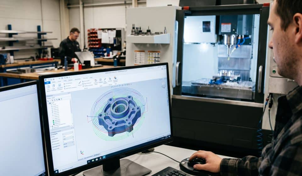
CAD/CAM Software: Turning Design Files Into Accurate Machine Toolpaths

The file an engineer sends me is never the part. Instead, it is a promise of a part. Between that clean solid model and a finished component, someone has to plan every move. A spinning piece of carbide has to travel through aluminum, steel, or titanium without breaking, rubbing, or chattering. It also has to stay clear of every vise jaw. Most of the time, that planning falls to me. The tool I lean on every day to do it is CAD CAM software.
I have spent most of my career as a CAM programmer. At first, I wrote code by hand at the control. Later I moved into the programming office, where the real planning happens. I have programmed three axis mills, lathes with live tooling, and five axis machines that cost more than most houses. Along the way, however, I learned one thing above all. The software does not make a programmer good. It makes a good programmer fast, and it makes a careless programmer dangerous.
This article is my honest look at how design files become accurate toolpaths. In addition, I will cover where the process tends to break down and what I check before anything runs on a spindle.
What CAD CAM Software Actually Does Between the Model and the Spindle
People outside the shop sometimes picture CAM as a big “make part” button. It is not. CAD CAM software is better described as a planning environment. In other words, it is where the programmer translates geometry into motion.
The CAD side holds the shape: faces, edges, holes, pockets, fillets, and the dimensions the designer intended. The CAM side, however, asks a different set of questions. What stock are we starting from? How will it be held? Which tools are in the carousel? In what order should material come off so the part stays rigid? How fast can each cutter safely go in this material?
A paper from the American Society for Engineering Education breaks the CAD/CAM process into a clear sequence. First you create the geometry. Then you assign toolpaths and cutting parameters. Finally, a post processor generates the G code for the machine controller. Of course, that is a fair summary on paper. In practice, each step hides a dozen decisions. As a result, each one affects whether the part comes off the machine in tolerance.
The output of all that planning is a toolpath. In fact, it is really just a long list of tool positions and the moves that connect them. The software calculates those positions from the model. At the same time, it accounts for the tool’s diameter, corner radius, and length. Then a post processor turns that neutral path into a specific dialect of G code. For example, a Haas, a Fanuc, a Siemens, and a Heidenhain each expect their own version.
Reading the Model in CAD CAM Software Like a Machinist
The most common mistakes I see do not happen in the toolpath at all. They happen in the first five minutes, when the model gets imported and nobody looks closely.
Which file formats CAD CAM software reads best
I always ask for a STEP file when I can get one. That is because STEP keeps true solid geometry. As a result, the software knows exactly where each surface sits instead of guessing from a pile of triangles. This overview on preparing CAD files for CNC work matches what I see daily. Simply put, STEP holds solid bodies reliably. IGES, on the other hand, often arrives as loose surface data, which leaves room for confusion during programming.
Mesh formats like STL are a different animal. They are fine for 3D printing, which is one reason the 3D printing vs. CNC machining decision changes which file you should ask for. However, a mesh approximates curves with flat facets. If the export tolerance was loose, my finishing pass now follows the wrong shape. On a cosmetic housing that might be acceptable. On a bearing bore, however, it is not.
Units, origin, and orientation
I once opened a file that came in at 25.4 times its real size. Apparently, someone had exported millimeters as inches. It sounds silly until it happens to you at 4:30 on a Friday. So before anything else, I measure a known feature and confirm the units. Then I check where the model’s origin sits relative to the part.
Files often arrive floating in space at an odd angle. This walkthrough on moving from STP files to G code makes the same point. After all, programming against a crooked model just means more time compensating later.
Checking the solid before CAD CAM software calculates paths
Small gaps between faces, sliver surfaces, and duplicate bodies confuse toolpath calculations. A finishing pass can dive into a gap that was never meant to be there. For that reason, I run whatever model check the software offers. Then I fix or flag problems before they become gouges.
A thread on Eng Tips about preparing CAD models for CAM shows other engineers share this habit. Specifically, they check the solid for errors before it reaches programming. After all, feature based CAM is only as accurate as the model feeding it.
CAD CAM Software Setup Is Where Accuracy Is Won or Lost
Once the model is trustworthy, I build the job setup. Admittedly, most tutorials rush through this part. Yet it decides whether the toolpaths will mean anything on the real machine.
Work coordinate system
The work coordinate system in CAD CAM software must match how the operator touches off the part. Say I program from the center of the stock. Now say the setup sheet tells the operator to pick up the back left corner. Consequently, every move in the program is now wrong by half the stock size. That is why I set program zero on a feature the operator can actually find. Ideally, an edge finder or probe should reach it easily. I also write it clearly on the setup sheet.
Stock definition
Modeling the raw stock accurately tells the software where material actually exists. That matters for two reasons, especially on tough jobs. First, it keeps the roughing toolpath from wasting time cutting air. Second, it lets the software calculate engagement correctly. Indeed, that is the foundation of modern roughing strategies.
Fixtures and workholding
I model the vise, the fixture plate, the clamps, and anything else in the work envelope. Granted, it takes extra time up front. But it is the only way simulation can warn me that a retract will clip a toe clamp. A toolpath that is perfect yet still hits the fixture is not accurate. Instead, it is just expensive.
Tool library with real holders
My tool library holds the real holder, stickout, and flute length of every cutter in the machine. Autodesk’s documentation for Adaptive Clearing describes options to include the shaft and holder in the calculation. Then the software keeps them a set clearance from the part. Those options are useless if the library holds a generic placeholder. I learned this the hard way on a deep pocket. The cutter cleared the wall perfectly, but the holder body rubbed the top of it.
CAD CAM Software Toolpath Strategies That Respect the Cutter
This is where CAD CAM software has changed the most since I started. Back then, roughing meant offset pocketing. The tool cut concentric loops that stepped over a fixed amount each pass. It worked, but every corner caused a spike in engagement. As a result, the cutter took a beating.
Adaptive and dynamic roughing
Modern adaptive strategies keep the tool’s radial engagement roughly constant. Of course, each vendor has its own name for them. The software peels and reroutes the tool so it never buries itself in a corner. Because the load stays steady, I can use most of the flute length in one axial pass. I can also push feed rates that would have been reckless with old pocketing.
Autodesk’s 2D Adaptive Clearing documentation notes that legacy clearing creates uneven engagement. By contrast, it says adaptive clearing can remove material around 40 percent faster. Deeper cuts become safe once those engagement spikes disappear. My own numbers vary by material and machine rigidity. Still, the direction is always the same. Tools last longer, cycle times drop, and the spindle sounds calmer.
Hurco’s guide on mastering toolpath strategies makes the same point from the machine builder side. It describes adaptive clearing as a way to keep cutting forces steady and reduce tool wear. Moreover, the benefit is greatest in tough materials and complex shapes.
Do not forget chip thinning
Light radial engagement has a catch that newer programmers often miss. When the width of cut drops below half the cutter diameter, the chip gets thinner. In fact, it becomes thinner than the feed per tooth you programmed. Sandvik Coromant explains this clearly in its material on chip thinning in milling.
If you do not raise the feed to compensate, the tool rubs instead of cutting. Meanwhile, heat builds at the edge, and tool life collapses. Most good CAD CAM software will calculate the compensation for you. Still, you need to understand why the feed number looks so high. So resist the urge to turn it down.
Rest machining
After a big roughing tool clears the bulk of the material, smaller tools take over. Typically, they clean out corners and narrow slots. Rest machining tells the software to look only at stock the previous tool could not reach. Done well, it saves a huge amount of time. That is because the small tool skips areas that are already finished. Done badly, it leaves islands of material behind. Then the finishing tool slams into them at full feed. Usually, this happens when the stock model does not reflect reality.
Finishing strategies matched to geometry
For finishing, I choose the strategy based on the surfaces in front of me. Steep walls usually get a contour or waterline path that steps down in Z. Shallow areas get parallel or scallop passes with a steady stepover. Many programs let me split a model by slope angle. I can then apply each strategy only where it works best. That control is one of the most valuable things CAD CAM software offers. Otherwise, a single strategy across a complex mold surface almost always leaves witness marks.
CAD CAM Software Tolerance, Chord Error, and Your Controller
This topic separates people who run CAM from people who understand it.
A CNC control moves in straight lines (G1) and arcs (G2 and G3). However, it does not natively understand a spline or a freeform surface. So the CAM system breaks curves into many short line segments. The Autodesk Adaptive Clearing reference explains this process and its trade off. Tighter tolerances give a more faithful shape. But they also create larger files, longer calculation times, and very short moves.
Those short moves cause a problem called data starving. Autodesk notes that older controls may process as few as 40 blocks per second. Newer ones, meanwhile, handle 1,000 or more. Feed tiny segments to a control at high speed, and it cannot keep up. Eventually, the machine starts hesitating between moves. Typically, you hear it as a stutter and see it as a blotchy finish.
My approach is simple. I set the machining tolerance to a fraction of the part tolerance. In short, I do not make it ten times tighter than needed. Where the control supports it, I turn on arc fitting. The software then swaps strings of tiny lines for smooth arcs. On high end five axis work, I rely on the control’s look ahead and smoothing functions. I also make sure the post processor actually turns them on. Accuracy is not only about how close the path sits to the model. It is also about whether the machine can run that path smoothly at the feed I asked for.
The Post Processor: Where Good Toolpaths Become Real G Code
Every CAM programmer has a post processor story. Mine involves a lathe that indexed its turret in a direction nobody expected. One line of posted code did not match what the machine builder intended.
The post processor translates between your toolpath and your machine. For instance, one control wants a certain tool change sequence. Another, meanwhile, calls work offsets its own way. A third handles rotary axes with unique logic. Even two machines with the same control brand may need different posts. It all depends on how the builder configured them.
Autodesk describes its CAMplete post processing and verification software as using customizable posts built with machine tool builders. These posts convert CAM output into safe NC code for three, four, and five axis machines. One detail matters for long term planning. Autodesk states that CAMplete will be fully retired on June 7, 2029. Meanwhile, those capabilities are moving into Fusion. It is a good reminder not to tie your post strategy to one product you cannot control.
What I insist on with any post:
- Safe startup blocks come before the first move. These cancel compensation, set the plane, and choose absolute positioning.
- Tool changes and retracts happen the way our operators expect, every time.
- Useful comments go into the code, such as the tool and operation name.
- Before production, the post is proven on that exact machine with a dry run and first article.
A generic post that “mostly works” is a liability. I would rather spend a day tuning a post than a week explaining a broken spindle.
CAD CAM Software Simulation: Check the Code That Actually Runs
Almost every modern CAD CAM software package includes toolpath simulation. For example, it shows material being removed, highlights gouges, and flags holder collisions. Naturally, I use it on every program. But I also know its limits.
Most built in simulation checks the toolpath before it goes through the post processor. The team behind MANUSsim explains this gap in their piece on external G code simulation. Basically, post processing happens separately from CAM simulation. So the final G code can differ from what you watched on screen. Post settings, machine parameters, and control configuration also play a part. In short, CAM simulation verifies the plan, not the instructions the machine will read.
This is not a new insight. IMS Software made the case back in 2004 in its announcement for integrated G code verification. Checking the posted code that will run on the machine is what gives real confidence.
For simple three axis jobs on a proven post, I trust the CAM simulation plus a careful single block first run. Higher risk work, however, is different. That includes five axis parts, mill turn parts, and anything with expensive material or long cycles. For those, I run the posted G code through a full machine simulation. That simulation uses an accurate kinematic model, essentially a digital twin of the machine, along with real fixtures and real tools. It catches overtravel on rotary axes and unexpected repositioning moves. Above all, it catches crashes that only appear when the machine unwinds an axis.
Five Axis and Mill Turn Work Raise the Stakes
Simultaneous five axis programming multiplies everything above. The software is no longer just moving a tool in X, Y, and Z. It is tilting and rotating the tool or the part. At the same time, it manages tool axis vectors to avoid gouging and keep the holder clear.
As a result, small decisions carry big consequences here. A tool axis that flips suddenly can whip the rotary table around at rapid speed. A tilt angle that looked fine at one end of a blade can drive the holder into the hub at the other. The best CAD CAM software gives me control over tilt limits and automatic tilting for collision avoidance. It also smooths the tool axis so the machine moves fluidly.
Mill turn adds another layer. Now I am syncing a main spindle, a sub spindle, turrets, and sometimes a B axis head. Therefore, the order and timing of operations matter as much as the paths. Machine simulation stops being optional on this kind of equipment. I will not send an untested mill turn program to the floor, period.
Automation in CAD CAM Software: Feature Recognition and Templates
Software vendors are pushing automation hard right now, and some of it is genuinely useful. Feature recognition can scan a model and find holes, pockets, and bosses automatically. Paired with a technology database, it can assign proven tools and cutting data in seconds.
SOLIDWORKS CAM, for example, offers tolerance based machining. It reads PMI data attached to the model and selects strategies to meet tolerance and finish needs. Especially on families of similar parts, that saves real hours. Javelin’s series on SOLIDWORKS CAM setup and toolpath generation shows how fast a good setup turns parameters into tool motion.
My honest view is that automation handles the repetitive 80 percent of the work very well. However, it does not replace judgment on the other 20 percent. Software can recognize a 10 millimeter hole. It does not know that the hole sits next to a thin wall that will spring if drilled too early. It also does not know that the customer only cares about that bore because it locates the whole assembly. The programmer still owns the strategy. I build templates from my own proven methods and let the software apply them. Even so, I review every operation before it posts.
Looking ahead, the industry has long talked about formats that carry more design intent into machining. The STEP NC standard was published as AP238 in 2007. Originally, it was designed to replace traditional ISO 6983 G codes. It links CNC process data to the full product description, tolerances included, the same record that PLM software manages upstream. Adoption has been slow, but the goal is right. After all, fewer translations mean fewer places for intent to get lost.
Choosing CAD CAM Software for a Real Shop
People ask me which package is “the best.” The honest answer is simple. The best CAD CAM software is the one that fits your machines, your parts, and your people. When I evaluate a system, I look at a few practical things.
First is post processor support for the exact machines on our floor. Ideally, those posts are also verified with the machine builder. Second is the quality of roughing and finishing strategies, especially adaptive roughing and rest machining. Third is how well it imports models from the CAD systems our customers use. Fourth is the depth of simulation, including posted G code with real machine kinematics. Fifth is how easily a team can build and share tool libraries and templates. Last is local support and training, because the software is only as good as its driver.
Cost matters, of course. But I have watched shops save a few thousand dollars on licensing. Later, they lost far more in scrap, broken tools, and spindle repairs. Pick the platform that helps your programmers make good decisions quickly. Then invest in their training.
What I Tell Every New Programmer
When someone new joins the programming office, I give them the same short list of habits. Measure the model before you trust it. Next, build the setup exactly as the operator will see it. Also, put real holders in your tool library. Understand why the software chose a feed rate, especially with chip thinning. Keep your tolerance sensible so the control can keep up. Never trust a post until it has been proven on that machine. Similarly, simulate the code that will actually run, not just the plan. And walk out to the shop floor to watch your program cut. The spindle will teach you things no screen ever will.
CAD CAM software has become remarkably capable. For example, it calculates in seconds what once took an afternoon of hand math. It also cuts parts faster and more safely than old pocketing loops ever could. But accuracy still comes from the person using it. Ultimately, the software turns a design file into a toolpath. The programmer turns that toolpath into a part someone can trust.
Frequently Asked Questions
What is CAD CAM software used for?
CAD CAM software turns a digital part design into machining instructions. First, the CAD portion defines geometry. Then the CAM portion creates toolpaths, applies cutting parameters, and outputs G code through a post processor. This ASEE paper on the CAD/CAM process outlines the typical sequence used in industry.
What file format is best for importing a design into CAM?
For most machining work, STEP is the preferred format because it keeps accurate solid geometry. IGES can work, although it often comes through as surfaces. STL meshes approximate curves with flat facets. See this guide on CAD file preparation for CNC for more detail.
What is adaptive clearing in CAM?
Adaptive clearing is a roughing strategy that keeps tool engagement steady by constantly adjusting the path. This allows deeper cuts and higher feeds with less tool wear. Autodesk’s Adaptive Clearing reference explains the settings for roughing and rest machining.
Why does a CNC machine stutter on some 3D finishing programs?
That is usually data starving. A program may contain many very short line segments at high feed rates. As a result, the control cannot process blocks fast enough and pauses between moves. Autodesk’s 2D Adaptive Clearing documentation explains how tolerance and control speed affect this.
What does a post processor do in CAD CAM software?
A post processor converts a CAM toolpath into G code formatted for a specific machine and control. Every machine is configured differently, so a proven post is essential for safe output. Autodesk’s CAMplete overview describes posts built with machine tool builders.
Is CAD CAM software simulation enough to prevent crashes?
Not always. Standard CAM simulation checks the toolpath before post processing. Therefore, the final G code can behave differently on the machine. This article on external G code simulation explains why checking the posted code adds a critical layer of safety.
What is chip thinning and why does it matter for toolpaths?
Chip thinning happens when the radial width of cut is less than half the cutter diameter. As a result, the actual chip becomes thinner than the programmed feed per tooth. Without feed compensation, the tool rubs and wears quickly. Sandvik Coromant covers this in its chip thinning training material.
References
- American Society for Engineering Education. Creating Part Programs Using the CAD/CAM Process
- Autodesk. Adaptive Clearing, Inventor CAM Help
- Autodesk. About 2D Adaptive Clearing, Inventor HSM Pro Help
- Autodesk. Autodesk Fusion with CAMplete: Post Processing and G Code Simulation
- Hurco. Mastering Toolpath Strategies: A CNC Machinist’s Guide to Efficiency
- Sandvik Coromant. The Importance of Chip Thinning in Machining
- MANUS Software on IndustryArena. Why Use External CNC Simulation for G Code Verification
- IMS Software. Integrated G Code Verification for Every CAM User
- Javelin Technologies. SOLIDWORKS CAM Standard Milling Setup: Generating Toolpaths
- SEACADTECH. Smart Manufacturing with SOLIDWORKS MBD and SOLIDWORKS CAM
- Wikipedia. STEP NC
- Eng Tips Forums. Best Practices to Prepare CAD Model for CAM
- Ecoreprap. Choosing and Preparing CAD Files for CNC Prototyping
- WANT. What Is an STP File and Why It Matters in CNC



[…] record covers far more than CAD files. In fact, it includes part numbers, the bill of materials, specifications, drawings, requirements, […]
[…] SLS 3D printing, a revision is a new file. You change the CAD on Monday and you can have updated parts the following week. For products in their first year on […]